Deep Reinforcement Learning for Autonomous Navigation on Duckietown Platform: Evaluation of Adversarial Robustness

Evaluating Adversarial Robustness in Duckietown Navigation

General Information

Deep RL for Autonomous Navigation on Duckietown Platform: Evaluation of Adversarial Robustness

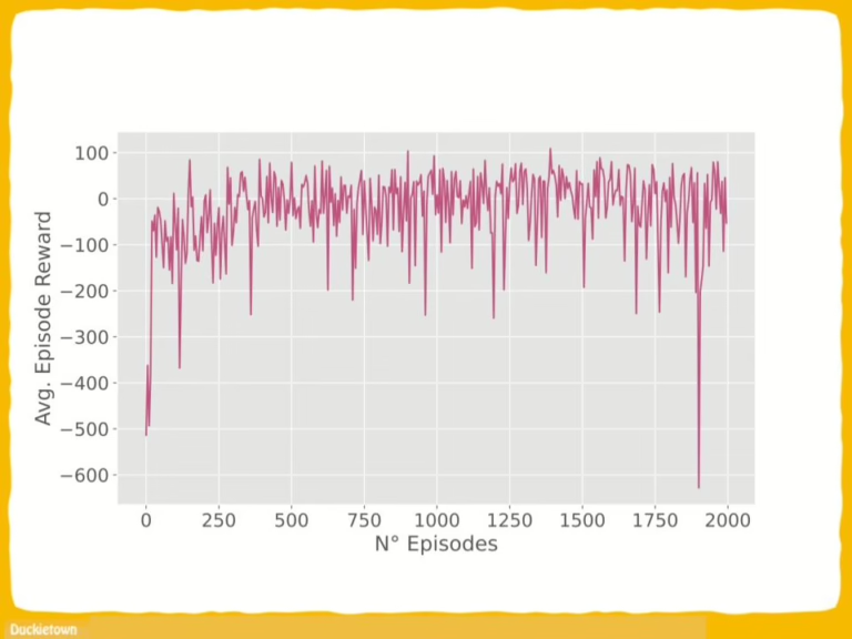
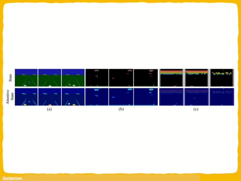
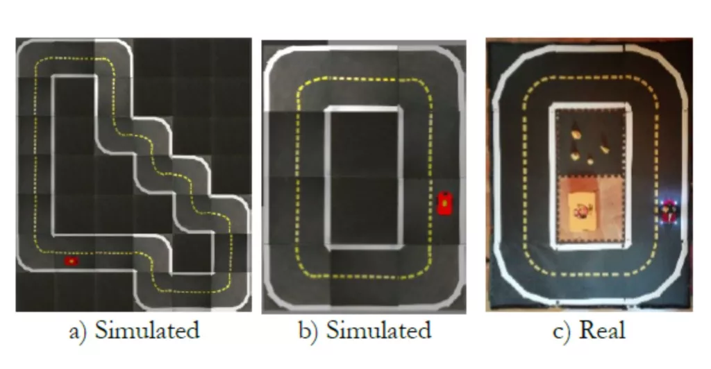
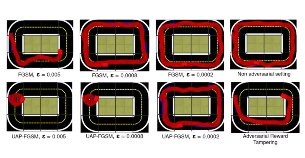
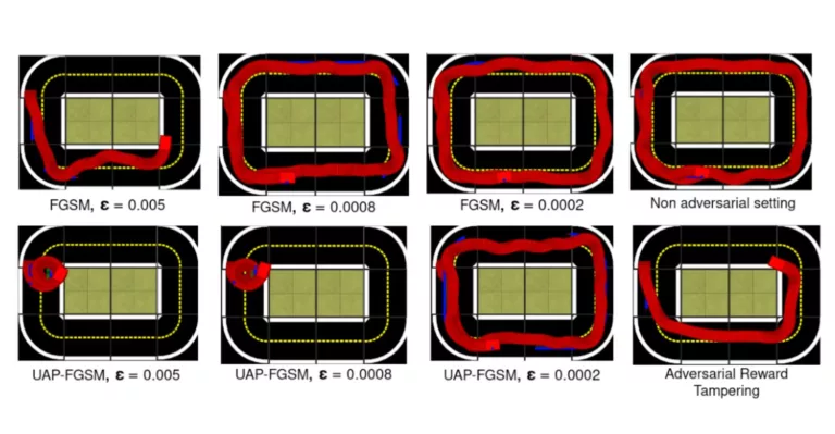
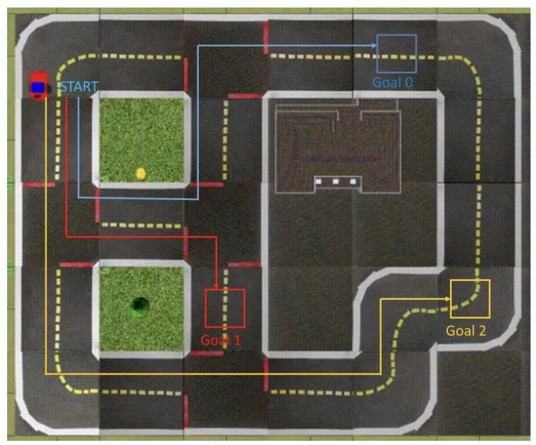
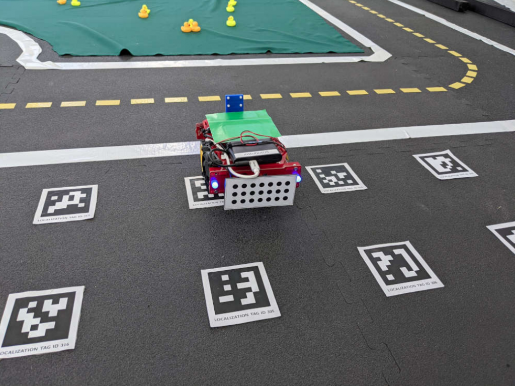
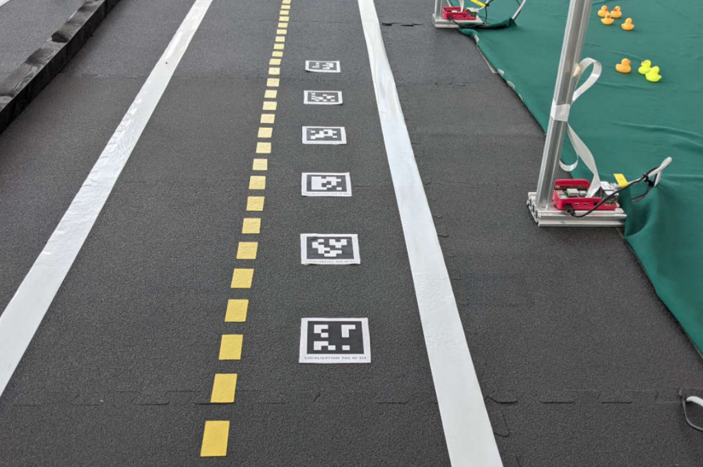
Adversarial Navigation Robustness - Sequence of robot positions with DRL agent trained under adversarial and non-adversarial settings in a lane following experiment. The UAPFGSM method, making the agent move in circular movements with minimal perturbations, while adversarial reward tampering forces it to move in the opposite direction of the road.

What is adversarial robustness in navigation tasks all about? A few important topics:

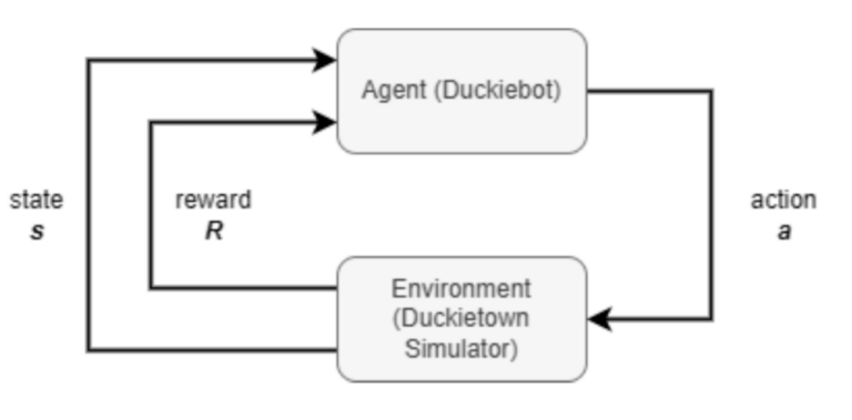
Reinforcement Learning (RL) is a type of machine learning where agents learn to make decisions by receiving rewards or penalties based on their actions in an environment. This is great because it removed the need for curated training datasets.

Deep Reinforcement Learning (DRL) enhances RL by using deep neural networks to process complex inputs and make decisions. Deep networks are neural networks with multiple layers.

Adversarial Robustness refers to a system’s ability to resist and maintain performance despite deliberate attacks or input perturbations.

Navigation is the task of finding feasible paths between points in the environment like Google Maps or similar systems provide us in everyday life. 

Learn about RL, navigation and other robot autonomy topics at the link below.

Abstract

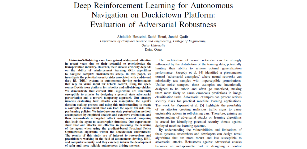
Self-driving cars have gained widespread attention in recent years due to their potential to revolutionize the transportation industry. However, their success critically depends on the ability of reinforcement learning (RL) algorithms to navigate complex environments safely. In this paper, we investigate the potential security risks associated with end-to-end deep RL (DRL) systems in autonomous driving environments that rely on visual input for vehicle control, using the open-source Duckietown platform for robotics and self-driving vehicles.

We demonstrate that current DRL algorithms are inherently susceptible to attacks by designing a general state adversarial perturbation and a reward tampering approach. Our strategy involves evaluating how attacks can manipulate the agent’s decision-making process and using this understanding to create a corrupted environment that can lead the agent towards low-performing policies. We introduce our state perturbation method, accompanied by empirical analysis and extensive evaluation, and then demonstrate a targeted attack using reward tampering that leads the agent to catastrophic situations.

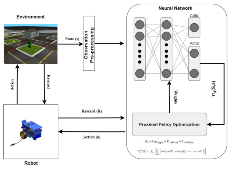
Our experiments show that our attacks are effective in poisoning the learning of the agent when using the gradient-based Proximal Policy Optimization algorithm within the Duckietown environment. The results of this study are of interest to researchers and practitioners working in the field of autonomous driving, DRL, and computer security, and they can help inform the development of safer and more reliable autonomous driving systems.

Highlights - Evaluation of Adversarial Robustness Results

Here is a visual tour of the work of the authors. For more details, check out the paper link.

Conclusion

Here are the conclusions from the authors of this paper:

“The focus of our study was to address adversarial attacks on deep reinforcement learning (DRL) agents, specifically examining state adversarial attacks and reward-tampering attacks. 

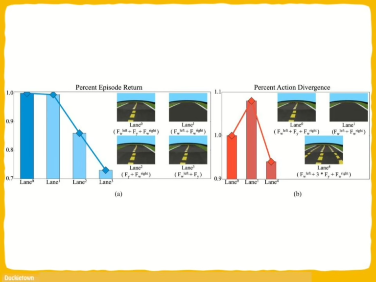
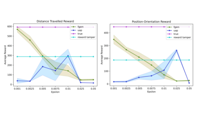
We developed a parametric framework for state adversarial attacks and a non-parametric framework for reward tampering attacks, which enabled us to create effective attacks. We found that the performance of a DRL agent declined rapidly after the attack, and the deviation from the road was worse than that of standard DRL. 

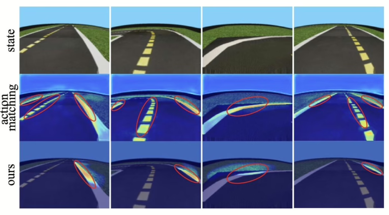
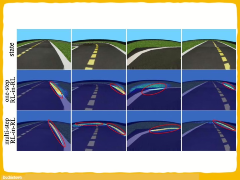
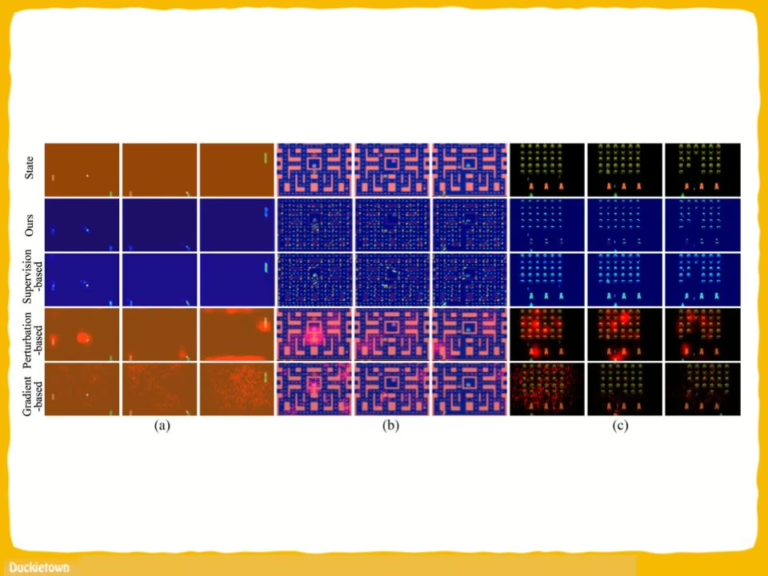
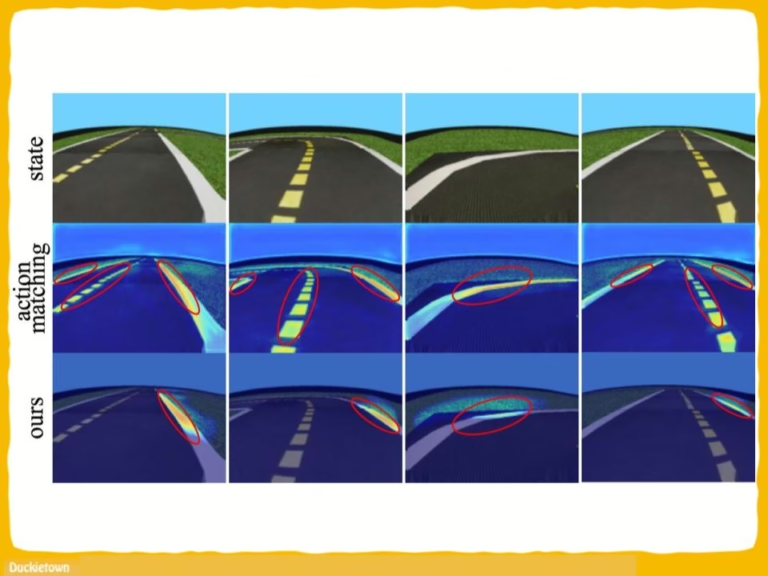
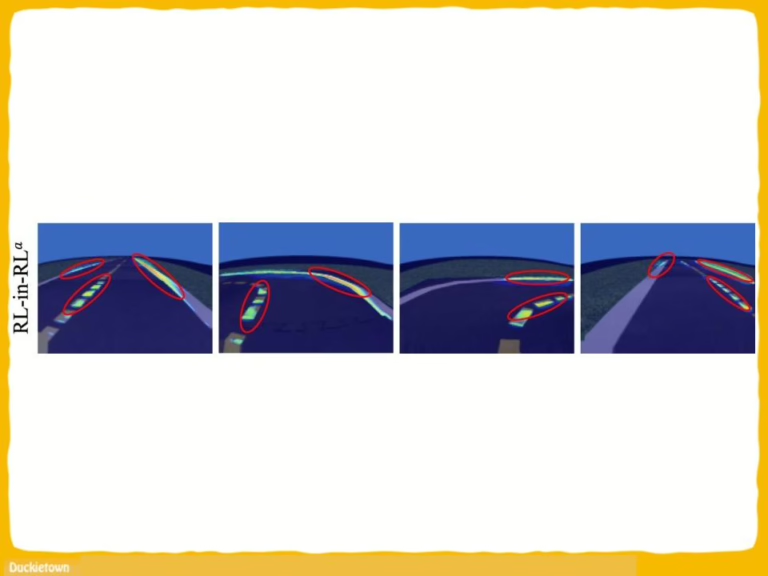
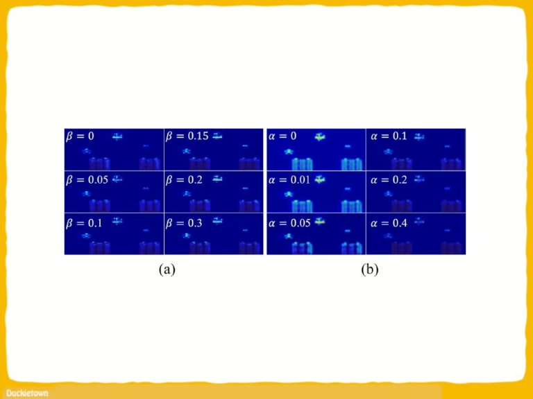
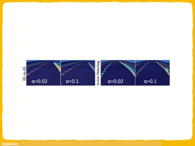
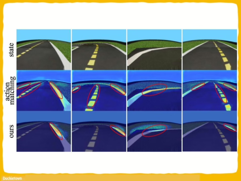
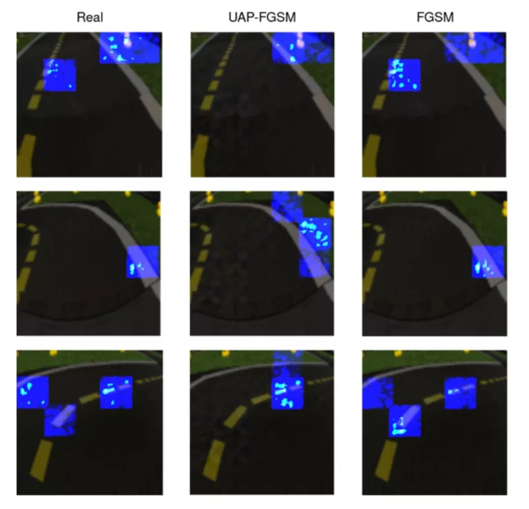
We used salient maps to provide a clear explanation of the policies’ internal operations in both the adversarial and non-adversarial aspects. Our research provides insight into the potential vulnerabilities of DRL agents and highlights the need for more robust and secure agents to mitigate the risk of adversarial attacks. 

Moving forward, future work will focus on incorporating real-world analysis to test the performance of the DuckieBot under both adversarial and non-adversarial settings”.

Project Authors

Abdullah Hosseini is a Research and Development Specialist at Weill Cornell Medicine in Qatar.

Junaid Qadir is a Professor of Computer Engineering at Qatar University.

Learn more

Duckietown is a platform for creating and disseminating robotics and AI learning experiences.

It is modular, customizable and state-of-the-art, and designed to teach, learn, and do research. From exploring the fundamentals of computer science and automation to pushing the boundaries of knowledge, Duckietown evolves with the skills of the user.

 

End-to-end Deep RL (DRL) systems: in autonomous driving environments that rely on visual input for vehicle control face potential security risks, including:

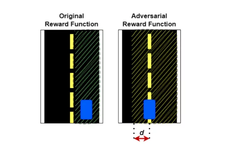
  • State Adversarial Perturbations: Subtle alterations to visual input that mislead the DRL agent, causing incorrect decision-making.
  • Reward Tampering: Manipulation of the reward signal to misguide the learning process, leading the agent to adopt unsafe or inefficient policies.

These vulnerabilities can compromise the safety and reliability of self-driving vehicles.

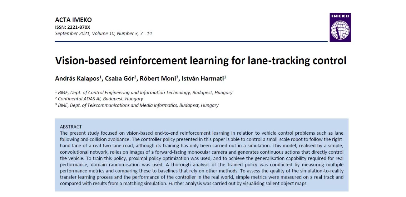
Visual deep reinforcement learning paper snippet

Vision-Based DRL Autonomous Driving Agent with Sim2Real Transfer

General Information

Vision-Based DRL Autonomous Driving Agent with Sim2Real Transfer

Vision-based DRL Autonomous Driving Agent with Sim2Real Transfer

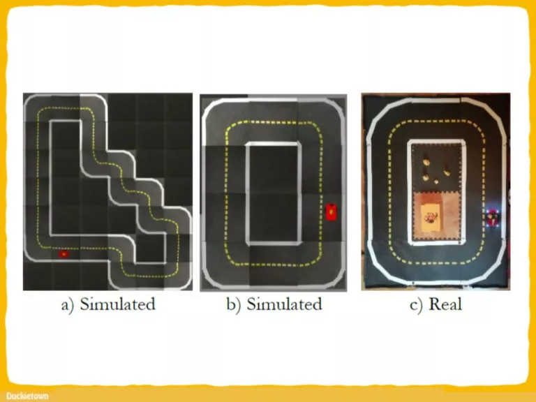
One way to obtain quick and cheap training data is to use simulation instead of real-world experiments. The question remains if the learnings of a simulation-trained agent apply to the real world. Sim2Real transfer is the field of research that studies this problem.

The challenge is particularly meaningful when using vision as the primary sensing capability for robots. Vision-based deep reinforcement learning (DRL) refers to a technique where ML agents, typically modeled as multi-layered neural networks, learn to “make decisions” directly from visual input. 

The essence of RL is training robotic agents based on policies that reward desirable outcomes. This family of techniques typically leads to increased adaptability to operational scenarios.

To learn about RL and its place in the larger context of robot autonomy, check out the resources below.

Abstract

To achieve fully autonomous driving, vehicles must be capable of continuously performing various driving tasks, including lane keeping and car following, both of which are fundamental and well-studied driving ones. However, previous studies have mainly focused on individual tasks, and car following tasks have typically relied on complete leader-follower information to attain optimal performance.

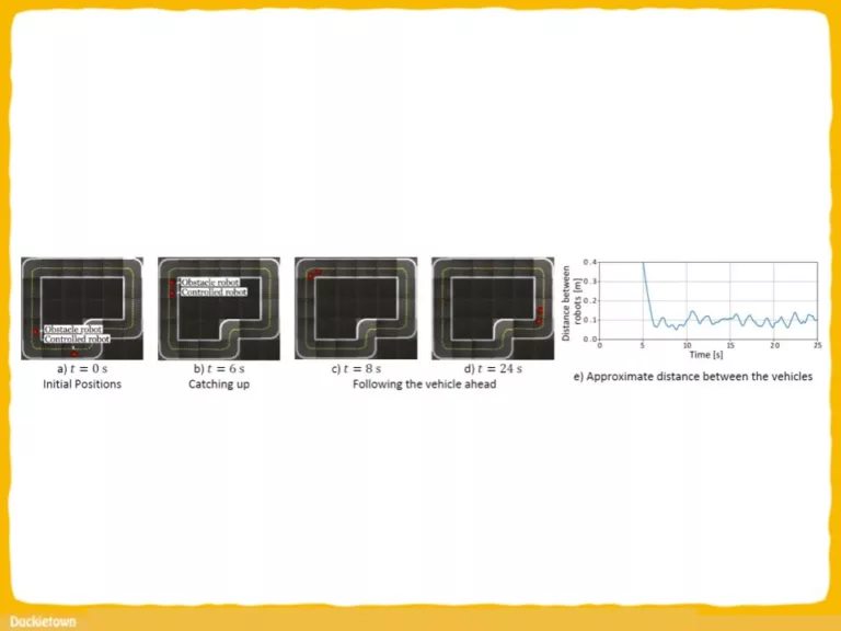
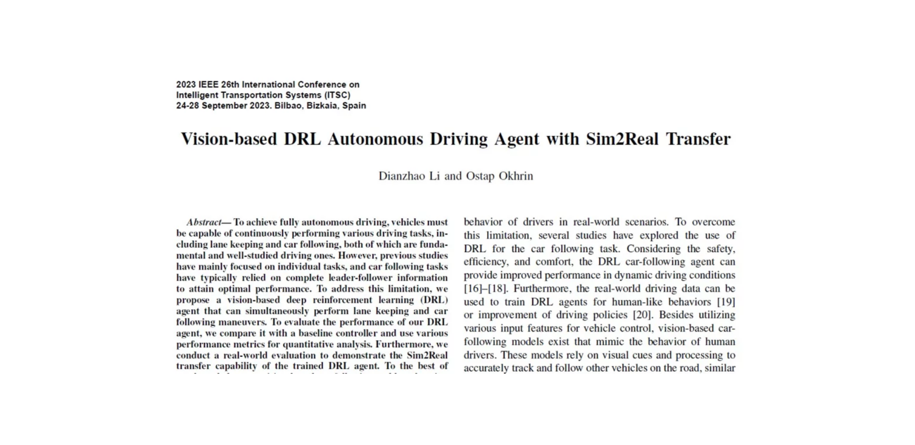
To address this limitation, we propose a vision-based deep reinforcement learning (DRL) agent that can simultaneously perform lane-keeping and car-following maneuvers.

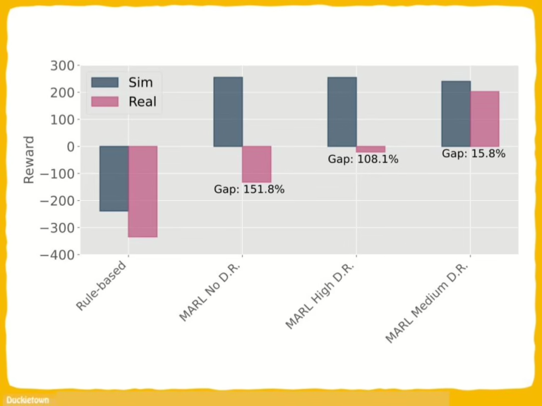
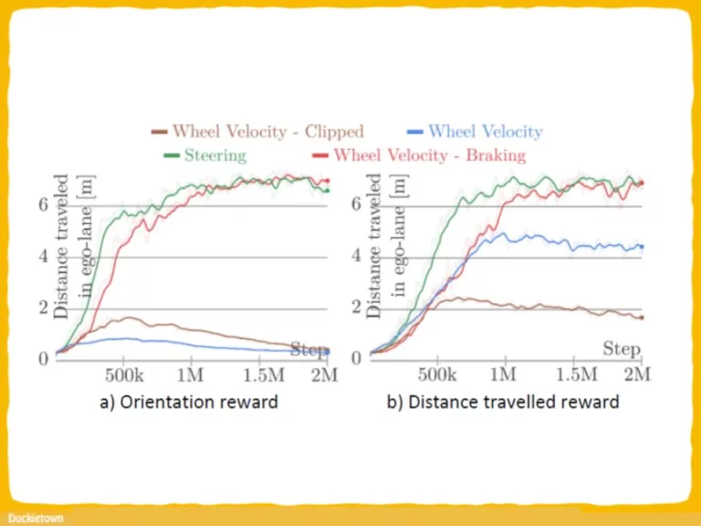
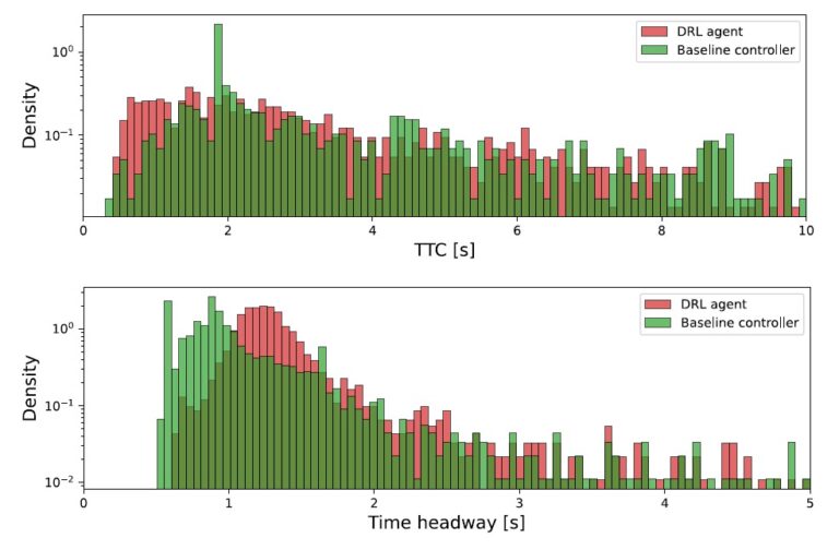
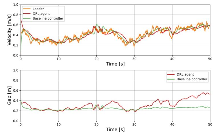
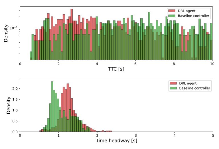
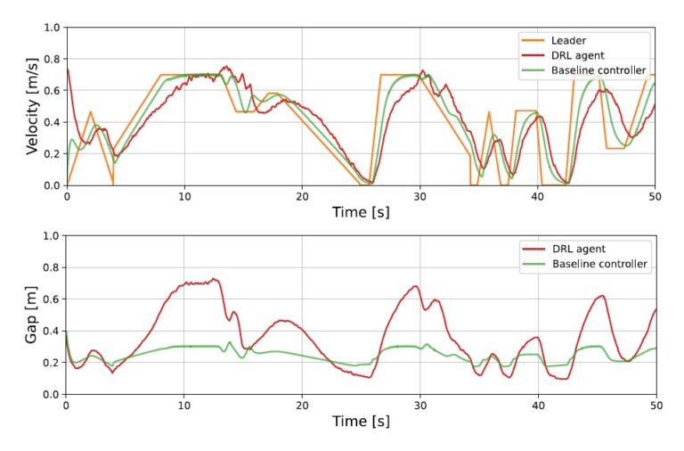
To evaluate the performance of our DRL agent, we compare it with a baseline controller and use various performance metrics for quantitative analysis. Furthermore, we conduct a real-world evaluation to demonstrate the Sim2Real transfer capability of the trained DRL agent.

To the best of our knowledge, our vision-based car following and lane-keeping agent with Sim2Real transfer capability is the first of its kind.

Highlights - Sim2Real transfer results

Here is a visual tour of the work of the authors. For all the details, check out the paper link.

Conclusion

This study proposes a vision-based DRL agent that can simultaneously perform lane-keeping and car-following tasks.

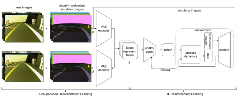
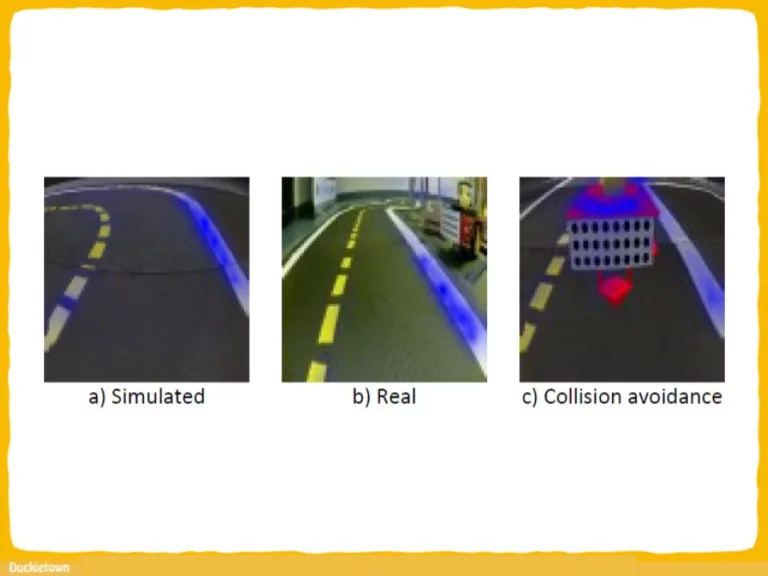
The overall system is divided into two modules: the perception module and the control module. The perception module extracts task-relevant attributes of the surroundings, while the control module is a DRL agent that takes these attributes as input. To evaluate the performance of the DRL agent, we compare it with a baseline algorithm in both simulation and real-world environments.

In the simulation, we compare the car following and lane-keeping capabilities of the DRL agent and baseline controller using various performance metrics. In the real-world environment, we demonstrate that the DRL agent can follow the leading vehicle while maintaining lane-keeping ability.

In future work, we plan to enhance our DRL agent by incorporating a comfort factor to address unstable driving behavior. Additionally, we aim to deploy more advanced algorithms for improved generalization.

Project Authors

Dianzhao Li is a research assistant at the Technische Universität Dresden, Dresden, Germany.

Ostap Okhrin is Chair of Statistics and Econometrics at the Institute of Economics and Transport, School of Transportation, Technische Universitat Dresden in Germany.

Learn more

Duckietown is a platform for creating and disseminating robotics and AI learning experiences.

It is modular, customizable and state-of-the-art, and designed to teach, learn, and do research. From exploring the fundamentals of computer science and automation to pushing the boundaries of knowledge, Duckietown evolves with the skills of the user.

Learning Skills to Navigate without a Master: A Sequential Multi-Policy Reinforcement Learning Algorithm snippet

Learning Skills to Navigate without a Master: A Sequential Multi-Policy Reinforcement Learning Algorithm

General Information

Learning Skills to Navigate without a Master: A Sequential Multi-Policy Reinforcement Learning Algorithm

Duckietown Reinforcement Learning Paper - Sequential path planning
Reinforcement learning (RL) is a rising star approach for developing autonomous robot agents. The essence of RL is training agents based on policies that reward desirable outcomes, which leads to increased adaptability to operational scenarios. Through iterations, robots refine their decision-making, optimizing actions based on rewards and penalties. This method provides robots with the flexibility to handle unpredictable situations, enhancing their efficiency and effectiveness in real-world tasks. To learn about RL with Duckietown, check out the resources below.

Abstract

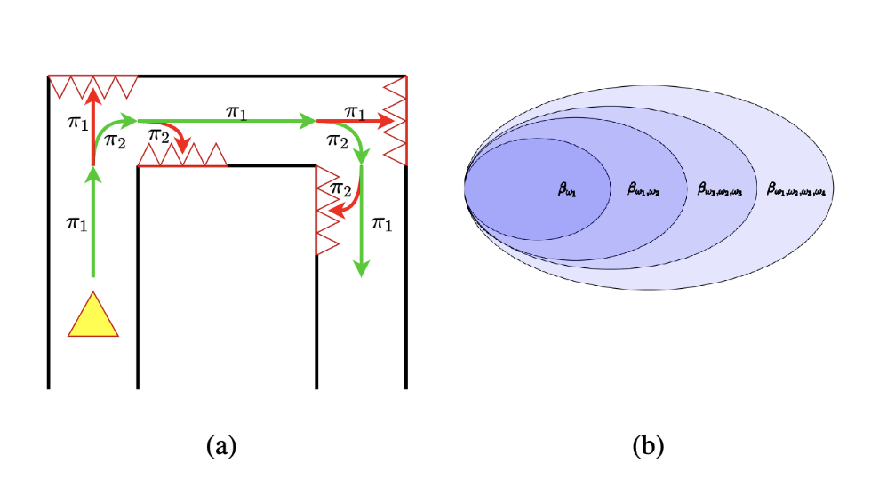
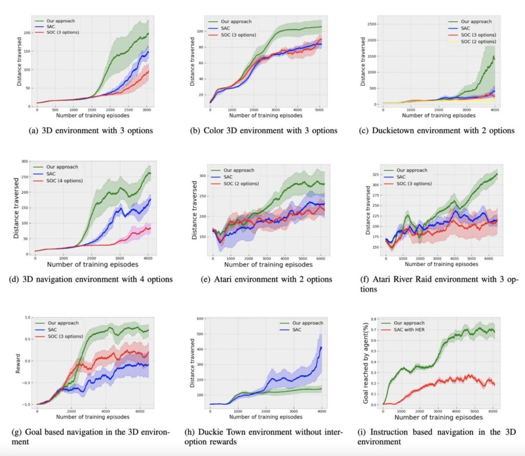
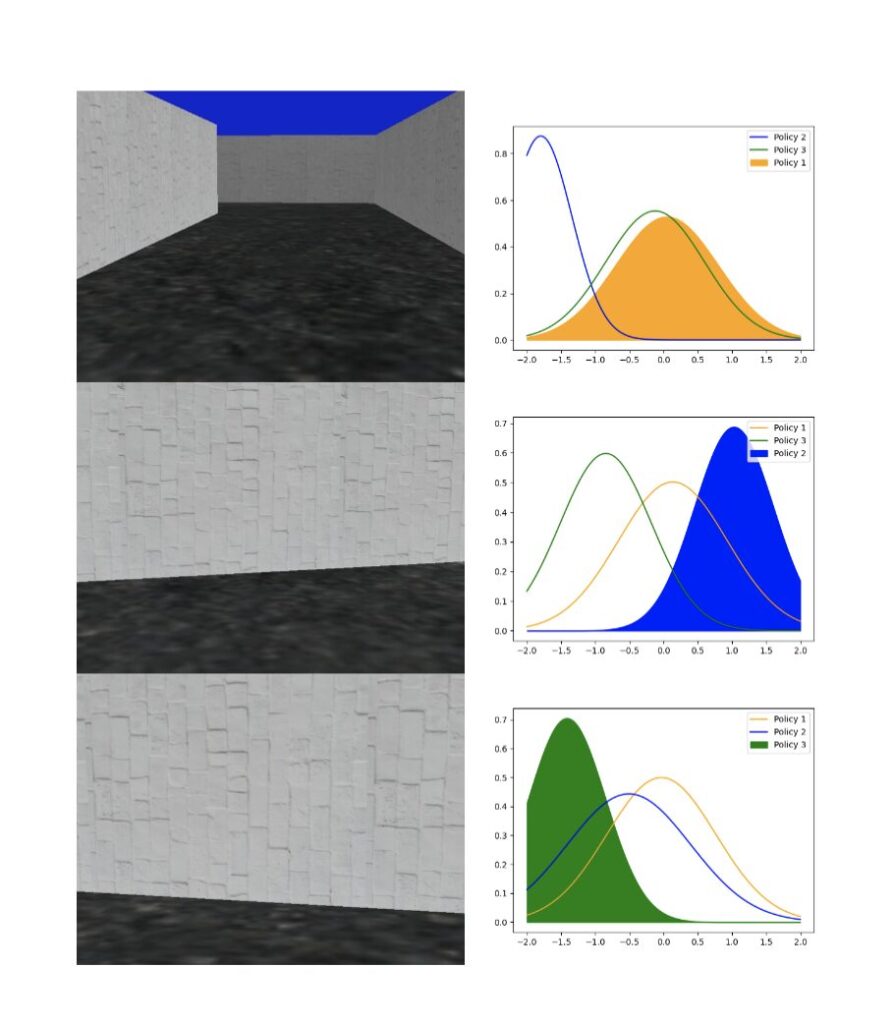
Solving complex problems using reinforcement learning necessitates breaking down the problem into manageable tasks, and learning policies to solve these tasks. These policies, in turn, have to be controlled by a master policy that takes high-level decisions. Hence learning policies involves hierarchical decision structures. However, training such methods in practice may lead to poor generalization, with either sub-policies executing actions for too few time steps or devolving into a single policy altogether. In our work, we introduce an alternative approach to learn such skills sequentially without using an overarching hierarchical policy. We propose this method in the context of environments where a major component of the objective of a learning agent is to prolong the episode for as long as possible. We refer to our proposed method as Sequential Soft Option Critic. We demonstrate the utility of our approach on navigation and goal-based tasks in a flexible simulated 3D navigation environment that we have developed. We also show that our method outperforms prior methods such as Soft Actor-Critic and Soft Option Critic on various environments, including the Atari River Raid environment and the Gym-Duckietown self-driving car simulator.
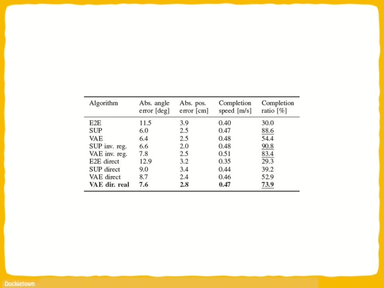
Highlights

Here is a visual tour of the work of the authors. 
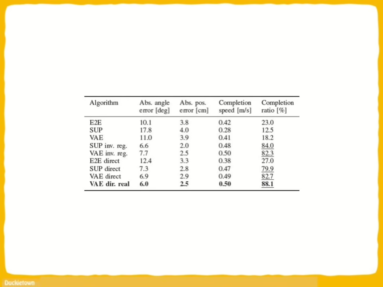
For all the details, check out the paper link!

Conclusion

In this paper, the authors proposed an algorithm called “Sequential Soft Option Critic” that allows adding new skills dynamically without the need for a higher-level master policy. This can be applicable to environments where a primary component of the objective is to prolong the episode. We show that this algorithm can be used to effectively incorporate diverse skills into an overall skill set, and it outperforms prior methods in several environments.

Learn more

Duckietown is a platform for creating and disseminating robotics and AI learning experiences.

Duckietown is modular, customizable and state-of-the-art. It is designed to teach, learn, and do research: from exploring the fundamentals of computer science and automation to pushing the boundaries of knowledge.

Monocular Robot Navigation with Self-Supervised Pretrained Vision Transformers

Monocular Robot Navigation with Self-Supervised Pre-trained Vision Transformers

Duckietown’s infrastructure is used by researchers worldwide to push the boundaries of knowledge. Of the many outstanding works published, today we’d like to highlight “Monocular Robot Navigation with Self-Supervised Pretrained Vision Transformers” by Saavedra-Ruiz et al. at the University of Montreal.

Using visual transformers (ViT) for understanding their surroundings, Duckiebots are made capable of detecting and avoiding obstacles, while safely driving inside lanes. ViT is an emerging machine vision technique that has its root in Natural Language Processing (NLP) applications. The use of this architecture is recent and promising in Computer Vision. Enjoy the read and don’t forget to reproduce these results on your Duckiebots!

Abstract

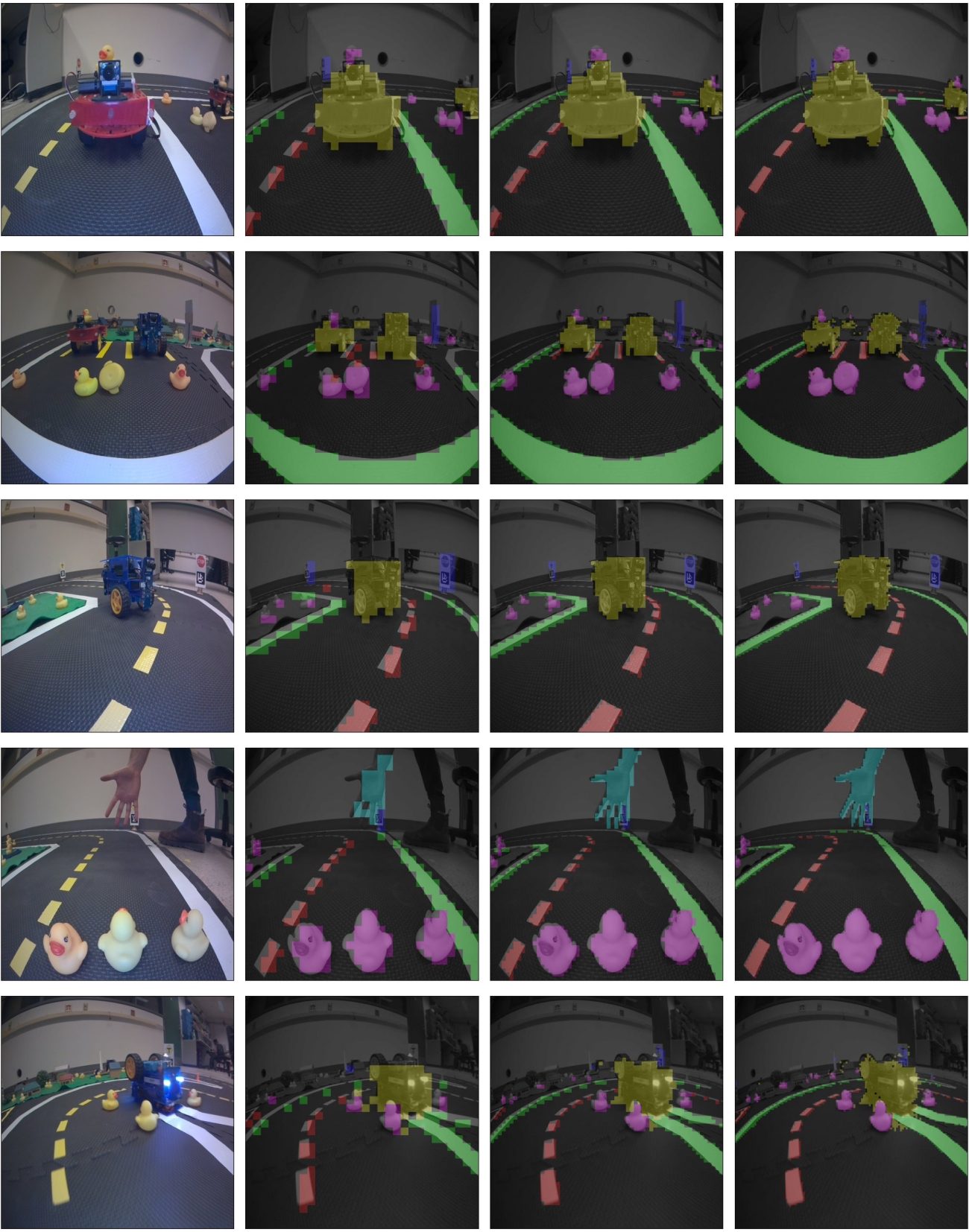
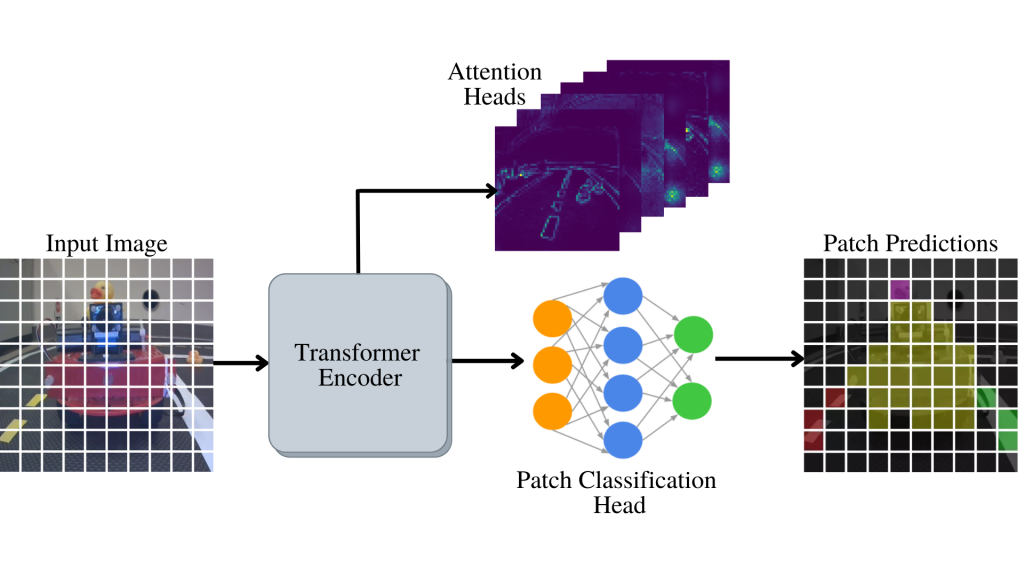
“In this work, we consider the problem of learning a perception model for monocular robot navigation using few annotated images. Using a Vision Transformer (ViT) pretrained with a label-free self-supervised method, we successfully train a coarse image segmentation model for the Duckietown environment using 70 training images. Our model performs coarse image segmentation at the 8×8 patch level, and the inference resolution can be adjusted to balance prediction granularity and real-time perception constraints. We study how best to adapt a ViT to our task and environment, and find that some lightweight architectures can yield good single-image segmentations at a usable frame rate, even on CPU. The resulting perception model is used as the backbone for a simple yet robust visual servoing agent, which we deploy on a differential drive mobile robot to perform two tasks: lane following and obstacle avoidance.”

Pipeline

“We propose to train a classifier to predict labels for every 8×8 patch in an image. Our classifier is a fully-connected network which we apply over ViT patch encodings to predict a coarse segmentation mask:”

Conclusions

“In this work, we study how embodied agents with visionbased motion can benefit from ViTs pretrained via SSL methods. Specifically, we train a perception model with only 70 images to navigate a real robot in two monocular visual-servoing tasks. Additionally, in contrast to previous SSL literature for general computer vision tasks, our agent appears to benefit more from small high-throughput models rather than large high-capacity ones. We demonstrate how ViT architectures can flexibly adapt their inference resolution based on available resources, and how they can be used in robotic application depending on the precision needed by the embodied agent. Our approach is based on predicting labels for 8×8 image patches, and is not well-suited for predicting high-resolution segmentation masks, in which case an encoder-decoder architecture should be preferred. The low resolution of our predictions does not seem to hinder navigation performance however, and we foresee as an interesting research direction how those high-throughput low-resolution predictions affect safety-critical applications. Moreover, training perception models in an SSL fashion on sensory data from the robot itself rather than generic image datasets (e.g., ImageNet) appears to be a promising research avenue, and is likely to yield visual representations that are better adapted to downstream visual servoing applications.”

Learn more

The Duckietown platform offers robotics and AI learning experiences.

Duckietown is modular, customizable and state-of-the-art. It is designed to teach, learn, and do research: from exploring the fundamentals of computer science and automation to pushing the boundaries of knowledge.

Automatic Wheels and Camera Calibration for Monocular and Differential Mobile Robots

Automatic Wheels and Camera Calibration for Monocular and Differential Mobile Robots

After assembling the robot, components such as the camera and wheels need to be calibrated. This requires human participation and depends on human factors. We describe the approach to fully automatic calibration of a robot’s camera and wheels.

The camera calibration collects the necessary set of images by automatically moving the robot in front of the chess boards, and then moving it on the marked floor, assessing its trajectory curvature. As a result of the calibration, coefficient k is calculated for the wheels, and camera matrix K (which includes the focal length, the optical center, and the skew coefficient) and distortion coefficients D are calculated for the camera. 

Proposed approach has been tested on duckiebots in Alexander Popov’s International Innovation Institute for Artificial Intelligence, Cybersecurity and Communication, SPbETU “LETI”. This solution is comparable to manual calibrations and is capable of replacing a human for this task. 

Camera calibration process

The initial position of the robot is a part of the floor with chessboards in front, where the robot is located from the very beginning, on which its camera is directed and the floorsurface is marked with aruco markers on the other side of it.

There can be any number of chessboards, determined by the amount of free space around the robot. To a greater extent, the accuracy of calibration is affected by the frames with different positions of the boards, e.g., boards located at different distances from the robot and at different angles. The physical size and type of all the boards around the robot must be the same.

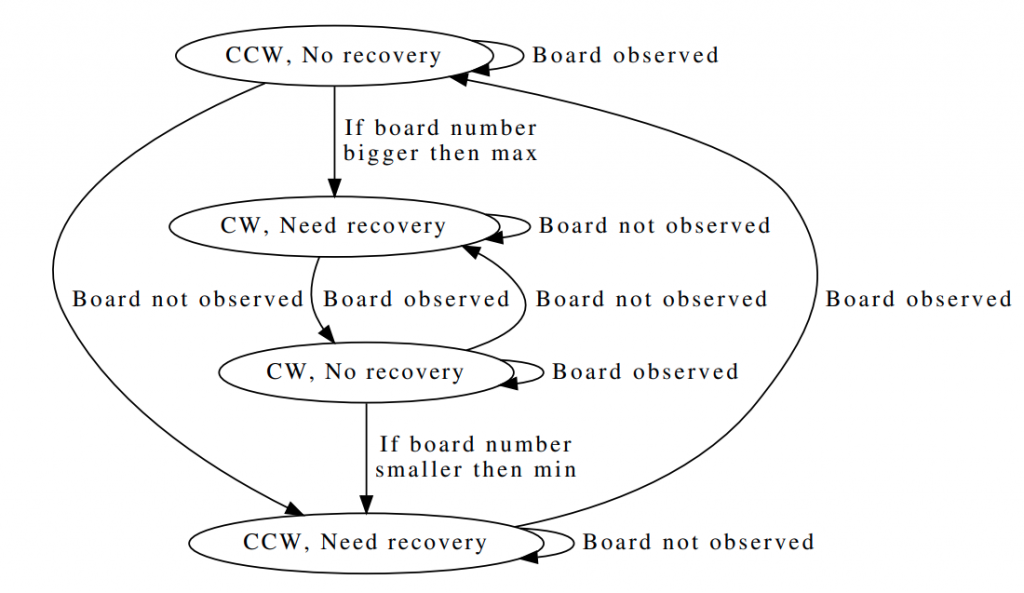
In fact, the camera calibration implies that the robot is rotating around its axis and taking pictures of all the viewable chessboards in turn. In this case, the ability to make several “passes” during the shooting process should be provided for, to control which of the boards the robot is currently observing and in which direction it should turn. As a result, the algorithm can be represented as a sequence of actions: “get a frame from the camera” and “turn” a littleThe final algorithm comprises the following sequence of actions:

  1. Obtain frame from the camera;
  2. Find a chessboard on the camera frame;
  3. Save information about board corners found in the image;
  4. Determine the direction of rotation according to the schedule;
  5. Make a step;
  6. Either repeat the steps described above, or complete the data
    collection and proceed with the camera calibration using OpenCV.


Wheels calibration process

Floor markers should be oriented towards the chessboards and begin as close to the robot as possible. The distance between the markers depends on camera’s resolution, as well as its height and angle of inclination, but it must be such that at least three recognizable markers can simultaneously be in the frame. For ours experiments, the distance between the markers was set as 15 cm with a marker size of 6.5 cm. The algorithm does not take into account the relative position of the markers against each other; however, the orientation of all markers must be strictly the same.

Let us consider the first iteration of the automatic wheel calibration algorithm:

  1. The robot receives the orientation of the marker closest to it and remembers it.
  2. Next, the robot moves forward with thespeeds of the left and right wheels equal to
    ω1ω2 for some fixed time t. The speeds are calculated taking into account the calibration
    coefficient k, which for the first iteration is chosen to equal 1 – that is, it is assumed that
    the real wheel speeds are equal.
  3. The robot obtains the orientation of the marker closest to it again and calculates the
    difference in angles between them.
  4. The coefficient ki for this step is calculated.
  5. The robot moves back for the same time t.

In order to reduce the influence of the error in calculating ki, coefficient k is refined only by the value of (ki−1)/2 after each iteration. It is important to complete this step after the robot moves back, because it reduces the chance of the robot moving outside the area width. If, after the next step, the modulus of the difference between (ki−1)/2 and 1.0 becomes less than the pre-selected E, then at this iteration (ki−1)/2 is not taken into account. If after three successive iterations ki is not taken into account, the wheel calibration is considered to be completed.

Accuracy Evaluation

To compare camera calibration errors, the knowledge of how to calculate these errors is needed. Since the calibration mechanism is used by the OpenCV library, the error is also calculated by the method offered by this library.

As noted earlier, with respect to calibration factors, the approach used to calibrate the camera is not applicable. Therefore, the influence of the coefficient on the robot’s trajectory curvature is estimated. To do this, the robot was located at a certain fixed distance from a straight line, along which it was oriented and then moved in manual mode strictly directly to a distance of two meters from the start point along the axis, relative to which it was oriented. Then, the robot stopped and the distance between the initial distance to the line and the final one was calculated.

Two metrices were estimated – reprojection error and straight line deviation. First one shows the quality of camera calibration, and the second one represents the quality of wheels calibration. Two pictures below present result of 10 independent tests in comparison with manual calibration.


The tests found that the suggested solution, on average, shows that the results are not much worse, than the classical manual solution when calibrating the camera, as well as when calibrating the wheels with a well known calibrated camera. However, when calibrating both the wheels and the camera, the wheel calibration can be significantly affected by the camera calibration effect. As a result of testing, a clear relationship was found between the reprojection error and the straight line deviation.

Method Modifications

After the integration of this approach, it became necessary to automate the last step-moving the robot to the field. Due to the fact that after the calibration step completion the robot becomes fully prepared for launching autonomous driving algorithms on it, the automation of this step further reduces the time spent by the operator when calibrating the robot, since instead of moving the robot to the field manually, he can place the next robot at the starting position. In our case, the calibration field was located at the side of the road lane so that the floor markers used to calibrate the wheels are oriented perpendicular to the road lane.

Thus, the first stage of the robot automatic removal from the calibration zone is to return its orientation back to the same state, as it was at the moment when the wheel calibration started. This was carried out using exactly the same approach that was described earlier—depending on the orientation of the floor marker closest to the robot, the robot rotates step by step about its axis clockwise or counterclockwise until the value of the robot’s orientation angle is modulo less than some preselected value.

At this point, the robot is still on the wheel calibration field, but in this case, it is oriented towards the lane. Thus, the last step is to move the robot outside the border of the field with markers. To do this, it is enough to give the robot a command to move directly until it stops observing the markers, when the last marker is hidden from the camera view. This means that the robot has left the calibration zone, and the robot can be put into the lane following mode.


Future Work

During the robot’s operation, the wheels calibration may become irrelevant. It can be influenced by various factors: a change in the wheel diameter due to wear of the wheel coating, a slight change in the characteristics of motors due to the wear of the gearbox plastic, and a change in the robot’s weight distribution, e.g., laying the cables on the other side of the case after charging the robot, and so a slight calibration mismatch can occur. However, all these factors have a rather small impact, and the robot will still have a satisfactory calibration. There is no need to re-perform the calibration process, just a little refinement of the current one seems to be enough. To do this, a section of the road along which the robots will be guaranteed to pass regularly, was selected. 

Further, markers were placed in this lane according to the rules described earlier: the distance between the markers is 15 cm; the size of the marker is 6.5 cm. The markers are located in the center of the lane. The distance between the markers may be not completely accurate, but they should be oriented in the same direction and co-directed with the movement in the lane on which they are placed. 

The first marker in the direction of travel must have a predefined ID. It can be anything, the only limitation is that it must be unique for a current robot environment. Further, the following changes were made to the algorithm for the standard control of the robot: when the robot recognizes the first marker with a predetermined ID while driving right in the lane, it corrects its orientation relative to this marker and continues to move strictly straight ahead. Further, the algorithm is similar to the one described earlier—the robot recognizing the next marker can refine its wheel calibration coefficient, apply it, and change the orientation coaxially with the next marker.
 

Conclusions

As a result, a solution was developed that allows a fully automatic calibration of the camera and the Duckiebot’s wheels. The main feature is the autonomy of the process, which allows one person to run the calibration of an arbitrary number of robots in parallel and not be blocked during their calibration. In addition, the robot is able to improve its calibration as it operates in default mode.

Comparing the developed solution with the initial one resulted in finding a slight deterioration in accuracy, which is primarily associated with the accuracy of the camera calibration; however, the result obtained is sufficient for the robot’s initial calibration and is comparable to manual calibration. 

Did you find this interesting?

Read more Duckietown based papers here.

Embedded out-of-distribution detection on an autonomous robot platform

Embedded out-of-distribution detection on an autonomous robot platform

Introduction

Machine learning is becoming more and more common in cyber-physical systems; many of these systems are safety critical, e.g. autonomous vehicles, UAVs, and surgical robots.  However, machine learning systems can only provide accurate outputs when their input data is similar to their training data.  For example, if an object detector in an autonomous vehicle is trained on images containing various classes of objects, but no ducks, what will it do when it encounters a duck during runtime?  One method for dealing with this challenge is to detect inputs that lie outside the training distribution of data: out-of-distribution (OOD) detection.  Many OOD detector architectures have been explored, however the cyber-physical domain adds additional challenges: hard runtime requirements and resource constrained systems.  In this paper, we implement a real-time OOD detector on the Duckietown framework and use it to demonstrate the challenges as well as the importance of OOD detection in cyber-physical systems.

Out-of-Distribution Detection

Machine learning systems perform best when their test data is similar to their training data.  In some applications unreliable results from a machine learning algorithm may be a mere nuisance, but in other scenarios they can be safety critical.  OOD detection is one method to ensure that machine learning systems remain safe during test time.  The goal of the OOD detector is to determine if the input sample is from a different distribution than that of the training data.  If an OOD sample is detected, the detector can raise a flag indicating that the output of the machine learning system should not be considered safe, and that the system should enter a new control regime.  In an autonomous vehicle, this may mean handing control back to the driver, or bringing the vehicle to a stop as soon as practically possible.

In this paper we consider the existing β-VAE based OOD detection architecture.  This architecture takes advantage of the information bottleneck in a variational auto-encoder (VAE) to learn the distribution of training data.  In this detector the VAE undergoes unsupervised training with the goal of minimizing the error between a true prior probability in input space p(z), and an approximated posterior probability from the encoder output p(z|x).  During test time, the Kullback-Leibler divergence between these distributions p(z) and q(z|x) will be used to assign an OOD score to each input sample.  Because the training goal was to minimize the distance between these two distributions on in-distribution data, in-distribution data found at runtime should have a low OOD score while OOD data should have a higher OOD score.

Duckietown

We used Duckietown to implement our OOD detector.  Duckietown provides a natural test bed because:
  • It is modular and easy to learn: the focus of our research is about implementing an OOD detector, not building a robot from scratch
  • It is a resource constrained system: the RPi on the DB18 is powerful enough to be capable of navigation tasks, but resource constrained enough that real-time performance is not guaranteed.  It servers as a good analog for a  system in which an OOD detector shares a CPU with perception, planning, and control software.
  • It is open source: this eliminates the need to purchase and manage licenses, allows us to directly check the source code when we encounter implementation issues, and allows us to contribute back to the community once our project is finished.
  • It is low-cost: we’re not made of money 🙂
 In our experiment, we used the stock DB18 robot.  Because we took advantage of the existing Duckietown framework, we only had to write three ROS nodes ourselves:
  • Lane following node: a simple OpenCV-based lane follower that navigates based on camera images.  This represents the perception and planning system for the mobile robot that we are trying to protect.  In our system the lane following node takes 640×480 RGB images and updates the planned trajectory at a rate of 5Hz.
  • OOD detection node: this node also takes images directly from the camera, but its job is to raise a flag when an OOD input appears (image with an OOD score greater than some threshold).  On the RPi with no GPU or TPU, it takes a considerable amount of time to make an inference on the VAE, so our detection node does not have a target rate, but rather uses the last available camera frame, dropping any frames that arrive while the OOD score is being computed.
  • Motor control node: during normal operation it takes the trajectory planned by the lane following node and sends it to the wheels.  However, if it receives a signal from the OOD detection node, it begins emergency breaking.

The Experiment

Our experiment considers the emergency stopping distance required for the Duckiebot when an OOD input is detected.  In our setup the Duckiebot drives forward along a straight track.  The area in front of the robot is divided into two zones: the risk zone and the safe zone.  The risk zone is an area where if an obstacle appears, it poses a risk to the Duckiebot.  The safe zone is further away and to the sides; this is a region where unknown obstacles may be present, but they do not pose an immediate threat to the robot.  An obstacle that has not appeared in the training set is placed in the safe zone in front of the robot.  As the robot drives forward along the track, the obstacle will eventually enter the risk zone.   Upon entry into the risk zone we measure how far the Duckiebot travels before the OOD detector triggers an emergency stop.

We defined the risk zone as the area 60cm directly in front of our Duckiebot.  We repeated the experiment 40 times and found that with our system architecture, the Duckiebot stopped on average 14.5cm before the obstacle.  However, in 5 iterations of the experiment, the Duckiebot collided with the stationary obstacle.

We wanted to analyze what lead to the collision in those five cases.  We started by looking at the times it took for our various nodes to run.  We plotted the distribution of end-to-end stopping times, image capture to detection start times, OOD detector execution times, and detection result to motor stop times.  We observed that there was a long tail on the OOD execution times, which lead us to suspect that the collisions occurred when the OOD detector took too long to produce a result.  This hypothesis was bolstered by the fact that even when a collision had occurred, the last logged OOD score was above the detection threshold, it had just been produced too late.  We also looked at the final two OOD detection times for each collision and found that in every case the final two times were above the median detector execution time.  This highlights the importance of real-time scheduling  when performing OOD detection in a cyber-physical system.

We also wanted to analyze what would happen if we adjusted the OOD detection threshold.  Because we had logged the the detection threshold every time the detector had run, we were able to interpolate the position of the robot at every detection time and discover when the robot would have stopped for different OOD detection thresholds.  We observe there is a tradeoff associated with moving the detection threshold.  If the detection threshold is lowered, the frequency of collisions can be reduced and even eliminated.  However, the mean stopping distance is also moved further from the obstacle and the robot is more likely to stop spuriously when the obstacle is outside of the risk zone.


Next Steps

In this paper we successfully implemented an OOD detector on a mobile robot, but our experiment leaves many more questions:

  • How does the performance of other OOD detector architectures compare with the β-VAE detector we used in this paper?
  • How can we guarantee the real-time performance of an OOD detector on a resource-constrained system, especially when sharing a CPU with other computationally intensive tasks like perception, planning, and control?
  • Does the performance vary when detecting more complex OOD scenarios: dynamic obstacles, turning corners, etc.?

Did you find this interesting?

Read more Duckietown based papers here.

Imitation Learning Approach for AI Driving Olympics Trained on Real-world and Simulation Data Simultaneously

Imitation Learning Approach for AI Driving Olympics Trained on Real-world and Simulation Data Simultaneously

The AIDO challenge is divided into two global stages: simulation and real-world. A single algorithm needs to perform well in both. It was quickly identified that one of the major problems is the simulation to real-world transfer. 

Many algorithms trained in the simulated environment performed very poorly in the real world, and many classic control algorithms that are known to perform well in a real-world environment, once tuned to that environment, do not perform well in the simulation. Some approaches suggest randomizing the domain for the simulation to real-world transfer.

We propose a novel method of training a neural network model that can perform well in diverse environments, such as simulations and real-world environment.

Dataset Generation

To that end, we have trained our model through imitation learning on a dataset compiled from four different sources:

  1. Real-world Duckietown dataset from logs.duckietown.com (REAL-DT).
  2. Simulation dataset on a simple loop map (SIM-LP).
  3. Simulation dataset on an intersection map (SIM-IS).
  4. Real-world dataset collected by us in our environment with car driven by PD controller (REAL-IH).

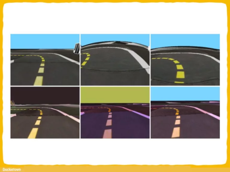
We aimed to collect data with as many possible situations such as twists in the road, driving in circles clockwise/counterclockwise, and so on. We have also tried to diversify external factors such as scene lighting, items in the room that can get into the camera’s field of view, roadside objects, etc. If we keep these conditions constant, our model may overfit to them and perform poorly in a different environment. For this reason, we changed the lighting and environment after each duckiebot run. The lane detection was calibrated for every lighting condition since different lighting changes the color scheme of the image input.

We made the following change to the standard PD algorithm: since most Duckietown turns and intersections are standard-shaped, we hard-coded the robot’s motion in these situations, but we did not exclude imperfect trajectories. For example, the ones that would go slightly out of bounds of the lane. Imperfections in the robot’s actions increase the robustness of the model. 

Neural network architecture and training

Original images are 640×480 RGB. As a preprocessing step, we remove the top third of the image, since it mostly contains the sky, resize the image to 64×32 pixels and convert it into the YUV colorspace.

We have used 5 convolutional layers with a small number of filters, followed by 2 fully-connected layers. The small size of the network is not only due to it being less prone to overfitting, but we also need a model that can run on a single CPU on RaspberryPi.

We have also incorporated Independent-Component (IC) layers. These layers aim to make the activations of each layer more independent by combining two popular techniques, BatchNorm and Dropout. For convolutional layers, we substitute Dropout with Spatial Dropout which has been shown to work better with them. The model outputs two values for voltages of the left and the right wheel drives. We use the mean square error (MSE) as our training loss.

Results

For the training evaluation, we compute the mean square error (MSE) of the left and the right wheels outputs on the validation set of each data source. 

The first table shows the results for the models trained on all data sources (HYBRID), on real-world data sources only (REAL) and on simulation data sources only (SIM). As we can see, while training on a single dataset sometimes achieves lower error on the same dataset than our hybrid approach. We can also see that our method performs on par with the best single methods. In terms of the average error it outperforms the closest one tenfold. This demonstrates definitively the high dependence of MSE on the training method, and highlights the differences between the data sources.

The next table shows simulation closed-loop performance for all our approaches using the Duckietown simulator. All methods drove for 15 seconds without major infractions, and the SIM model that was trained specifically on the simulation data only drove just 1.8 tiles more than our hybrid approach.

The third table shows the closed-loop performance in the real-world environment. Comparing the number of tiles, we see that our hybrid approach drove about 3.5 tiles more than the following in the rankings model trained on real-world data only.

Conclusion

Our method follows the imitation learning approach and consists of a convolutional neural network which is trained on a dataset compiled from data from different sources, such as simulation model and real-world Duckietown vehicle driven by a PD controller, tuned to various conditions, such as different map configuration and lighting. 

We believe that our approach of emphasizing neurons independence and monitoring generalization performance can offer more robustness to control models that have to perform in diverse environments. We also believe that the described approach of imitation learning on data obtained from several algorithms that are fitted to specific environments may yield a single algorithm that will perform well in general.

 —
 JBRRussia1 team

Integrated Benchmarking and Design for Reproducible and Accessible Evaluation of Robotic Agents

Integrated Benchmarking and Design for Reproducible and Accessible Evaluation of Robotic Agents

Why is this important?

As robotics matures and increases in complexity, it is more necessary than ever that robot autonomy research be reproducible.

Compared to other sciences, there are specific challenges to benchmarking autonomy, such as the complexity of the software stacks, the variability of the hardware and the reliance on data-driven techniques, amongst others.

We describe a new concept for reproducible robotics research that integrates development and benchmarking, so that reproducibility is obtained by design from the beginning of the research/development processes.

We first provide the overall conceptual objectives to achieve this goal and then a concrete instance that we have built: the DUCKIENet.

The Duckietown Automated Laboratories (Autolabs)

One of the central components of this setup is the Duckietown Autolab (DTA), a remotely accessible standardized setup that is itself also relatively low-cost and reproducible.

DTAs include an off-the-shelf camera-based localization system. The accessibility of the hardware testing environment through enables experimental benchmarking that can be performed on a network of DTAs in different geographical locations.

The DUCKIENet

When evaluating agents, careful definition of interfaces allows users to choose among local versus remote evaluation using simulation, logs, or remote automated hardware setups. The Decentralized Urban Collaborative Benchmarking Environment Network (DUCKIENet) is an instantiation of this design based on the Duckietown platform that provides an accessible and reproducible framework focused on autonomous vehicle fleets operating in model urban environments. 

The DUCKIENet enables users to develop and test a wide variety of different algorithms using available resources (simulator, logs, cloud evaluations, etc.), and then deploy their algorithms locally in simulation, locally on a robot, in a cloud-based simulation, or on a real robot in a remote lab. In each case, the submitter receives feedback and scores based on well-defined metrics.

Validation

We validate the system by analyzing the repeatability of experiments conducted using the infrastructure and show that there is low variance across different robot hardware and across different remote labs. We built DTAs at the Swiss Federal Institute of Technology in Zurich (ETHZ) and at the Toyota Technological Institute at Chicago (TTIC).

Conclusions

Our contention is that there is a need for stronger efforts towards reproducible research for robotics, and that to achieve this we need to consider the evaluation in equal terms as the algorithms themselves. In this fashion, we can obtain reproducibility by design through the research and development processes. Achieving this on a large-scale will contribute to a more systemic evaluation of robotics research and, in turn, increase the progress of development.

If you found this interesting, you might want to:

Robust Reinforcement Learning-based Autonomous Driving Agent for Simulation and Real World

Robust Reinforcement Learning-based Autonomous Driving Agent for Simulation and Real World

We asked Róbert Moni to tell us more about his recent work. Enjoy the read!

The author's perspective

Most of us, proud nerd community members, experience driving first time by the discrete actions taken on our keyboards. We believe that the harder we push the forward arrow (or the W-key), the car from the game will accelerate faster (sooo true 😊 ). Few of us believes that we can resolve this task with machine learning. Even fever of us believes that this can be done accurately and in a robust mode with a basic Deep Reinforcement Learning (DRL) method known as Deep Q-Learning Networks (DQN).

It turned to be true in the case of a Duckiebot, and even more, with some added computer vision techniques it was able to perform well both in simulation (where the training process was carried out) and real world.

The pipeline

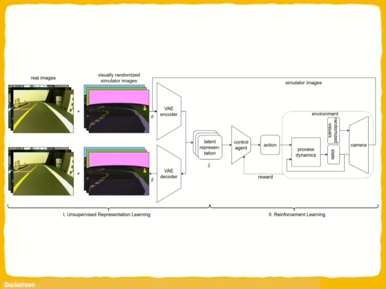
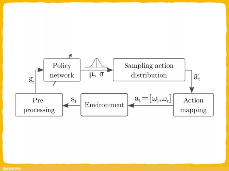
The complete training pipeline carried out in the Duckietown-gym environment is visualized in the figure above and works as follows. First, the camera images go through several preprocessing steps:

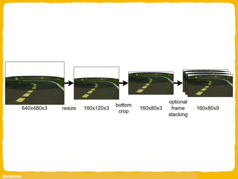
  • resizing to a smaller resolution (60×80) for faster processing;
  • cropping the upper part of the image, which doesn’t contain useful information for the navigation;
  • segmenting important parts of the image based on their color (lane markings);
  • and normalizing the image;
  • finally a sequence is formed from the last 5 camera images, which will be the input of the Convolutional Neural Network (CNN) policy network (the agent itself).

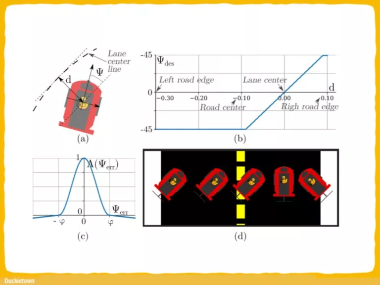
The agent is trained in the simulator with the DQN algorithm based on a reward function that describes how accurately the robot follows the optimal curve. The output of the network is mapped to wheel speed commands.

The workings

The CNN was trained with the preprocessed images. The network was designed such that the inference can be performed real-time on a computer with limited resources (i.e. it has no dedicated GPU). The input of the network is a tensor with the shape of (40, 80, 15), which is the result of stacking five RGB images. The network consists of three convolutional layers, each followed by ReLU (nonlinearity function) and MaxPool (dimension reduction) operations.

The convolutional layers use 32, 32, 64 filters with size 3 × 3. The MaxPool layers use 2 × 2 filters. The convolutional layers are followed by fully connected layers with 128 and 3 outputs. The output of the last layer corresponds to the selected action. The output of the neural network (one of the three actions) is mapped to wheel speed commands; these actions correspond to turning left, turning right, or going straight, respectively.

Learn more

Our work was acknowledged and presented at the IEEE World Congress on Computational Intelligence 2020 conference. We plan to publish the source code after AI-DO5 competition. Our paper is available on ieeexplore.ieee.org, deepai.org and arxiv.org.

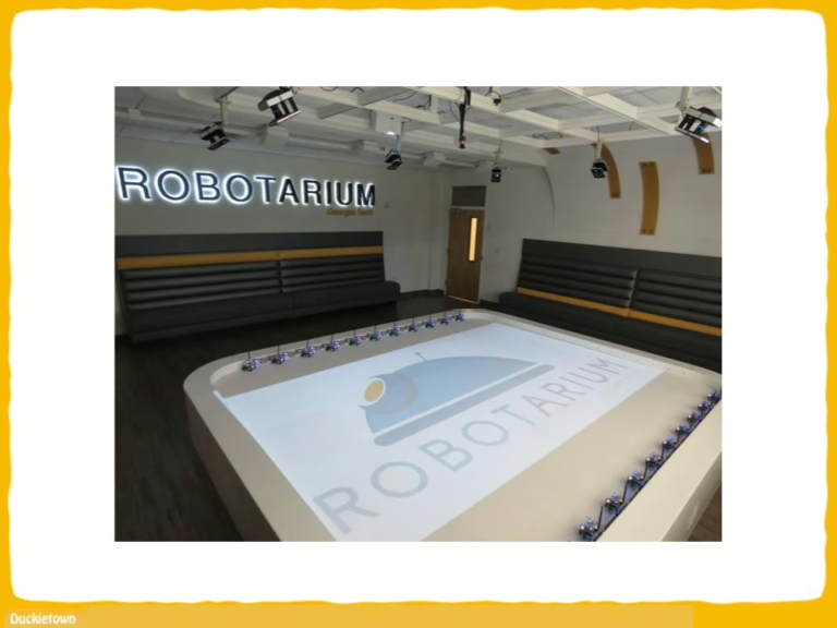
Check out our sim and real demo on Youtube performed at our Duckietown Robotarium put together at Budapest University of Technology and Economics. .

Interactive Learning with Corrective Feedback for Policies based on Deep Neural Networks

Interactive Learning with Corrective Feedback for Policies based on Deep Neural Networks

Deep Reinforcement Learning (DRL) has become a powerful strategy to
solve complex decision making problems based on Deep Neural Networks (DNNs).

However, it is highly data demanding, so unfeasible in physical systems for most
applications. In this work, we approach an alternative Interactive Machine Learning (IML) strategy for training DNN policies based on human corrective feedback,
with a method called Deep COACH (D-COACH). This approach not only takes advantage of the knowledge and insights of human teachers as well as the power of
DNNs, but also has no need of a reward function (which sometimes implies the
need of external perception for computing rewards). We combine Deep Learning
with the COrrective Advice Communicated by Humans (COACH) framework, in
which non-expert humans shape policies by correcting the agent’s actions during
execution. The D-COACH framework has the potential to solve complex problems
without much data or time required. 

Experimental results validated the efficiency of the framework in three different problems (two simulated, one with a real robot),with state spaces of low and high dimensions, showing the capacity to successfully learn policies for continuous action spaces like in the Car Racing and Cart-Pole problems faster than with DRL.

Introduction

Deep Reinforcement Learning (DRL) has obtained unprecedented results in decisionmaking problems, such as playing Atari games [1], or beating the world champion inGO [2]. 

Nevertheless, in robotic problems, DRL is still limited in applications with
real-world systems [3]. Most of the tasks that have been successfully addressed with
DRL have two common characteristics: 1) they have well-specified reward functions, and 2) they require large amounts of trials, which means long training periods
(or powerful computers) to obtain a satisfying behavior. These two characteristics
can be problematic in cases where 1) the goals of the tasks are poorly defined or
hard to specify/model (reward function does not exist), 2) the execution of many
trials is not feasible (real systems case) and/or not much computational power or
time is available, and 3) sometimes additional external perception is necessary for
computing the reward/cost function.

On the other hand, Machine Learning methods that rely on transfer of human
knowledge, Interactive Machine Learning (IML) methods, have shown to be time efficient for obtaining good performance policies and may not require a well-specified
reward function; moreover, some methods do not need expert human teachers for
training high performance agents [4–6]. In previous years, IML techniques were
limited to work with low-dimensional state spaces problems and to the use of function approximation such as linear models of basis functions (choosing a right basis
function set was crucial for successful learning), in the same way as RL. But, as
DRL have showed, by approximating policies with Deep Neural Networks (DNNs)
it is possible to solve problems with high-dimensional state spaces, without the need
of feature engineering for preprocessing the states. If the same approach is used in
IML, the DRL shortcomings mentioned before can be addressed with the support of
human users who participate in the learning process of the agent.
This work proposes to extend the use of human corrective feedback during task
execution to learn policies with state spaces of low and high dimensionality in continuous action problems (which is the case for most of the problems in robotics)
using deep neural networks.

We combine Deep Learning (DL) with the corrective advice based learning
framework called COrrective Advice Communicated by Humans (COACH) [6],
thus creating the Deep COACH (D-COACH) framework. In this approach, no reward functions are needed and the amount of learning episodes is significantly reduced in comparison to alternative approaches. D-COACH is validated in three different tasks, two in simulations and one in the real-world.

Conclusions

This work presented D-COACH, an algorithm for training policies modeled with
DNNs interactively with corrective advice. The method was validated in a problem
of low-dimensionality, along with problems of high-dimensional state spaces like
raw pixel observations, with a simulated and a real robot environment, and also
using both simulated and real human teachers.

The use of the experience replay buffer (which has been well tested for DRL) was
re-validated for this different kind of learning approach, since this is a feature not
included in the original COACH. The comparisons showed that the use of memory
resulted in an important boost in the learning speed of the agents, which were able
to converge with less feedback, and to perform better even in cases with a significant
amount of erroneous signals.

The results of the experiments show that teachers advising corrections can train
policies in fewer time steps than a DRL method like DDPG. So it was possible
to train real robot tasks based on human corrections during the task execution, in
an environment with a raw pixel level state space. The comparison of D-COACH
with respect to DDPG, shows how this interactive method makes it more feasible
to learn policies represented with DNNs, within the constraints of physical systems.
DDPG needs to accumulate millions of time steps of experience in order to obtain

Did you find this interesting?

Read more Duckietown based papers here.