


 - Duckietown")


 - Duckietown")


")

 - Duckietown")
Westminster, Maryland: MAGIC and Duckietown partner to bring robot autonomy education in Westminster, MD.
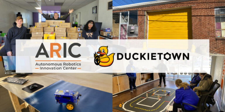
The Mid-Atlantic Gigabit Innovation Collaboratory (MAGIC) was awarded funding from the Knorr-Bremse Global Care program in July of 2022 to launch an Autonomous Robotics Innovation Center (ARIC) in the heart of downtown Westminster.
Their goal for ARIC is to use the Duckietown platform to give Westminster students industry-relevant skills and hands-on experience that will prepare them for careers or further learning in robotics and engineering.
We are very pleased to announce our partnership with MAGIC, bringing the Duckietown platform to Carroll County students and introducing the local community to robotics and AI technology.
MAGIC is a 501(c)3 non-profit organization headquartered in Westminster, MD, USA. Their mission is to build a technological ecosystem that creates and nurtures talent, entrepreneurship, and tech businesses, elevating the Westminster Gigabit community to lead the Mid-Atlantic region.
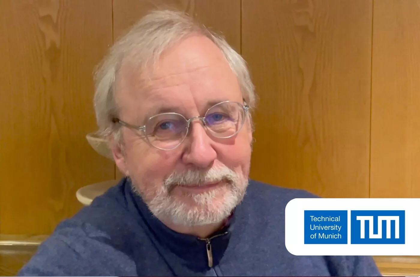
We talked with Graham Dodge, Executive Director of MAGIC, to know more about their new Autonomous Robotics Innovation Center (ARIC) project and how Duckietown is being used in this context.


My name is Graham Dodge. I’m the executive director of Magic Inc., a 501(c)3 non-profit based in Maryland, United States. We focus on technology, education, and workforce development within our community.
I was speaking with the CEO of a local company called Dynamic Dimension Technologies. We were discussing our autonomous corridor project in the city of Westminster, Maryland. He recommended using Duckietown as a platform to demonstrate some of the technologies to local elected officials and stakeholders. After seeing videos of Duckietown on their website, I was impressed by its user-friendly and cute approach to making technology accessible to people unfamiliar with computer vision and robotics. It seemed like a perfect way to explain these concepts to our community.
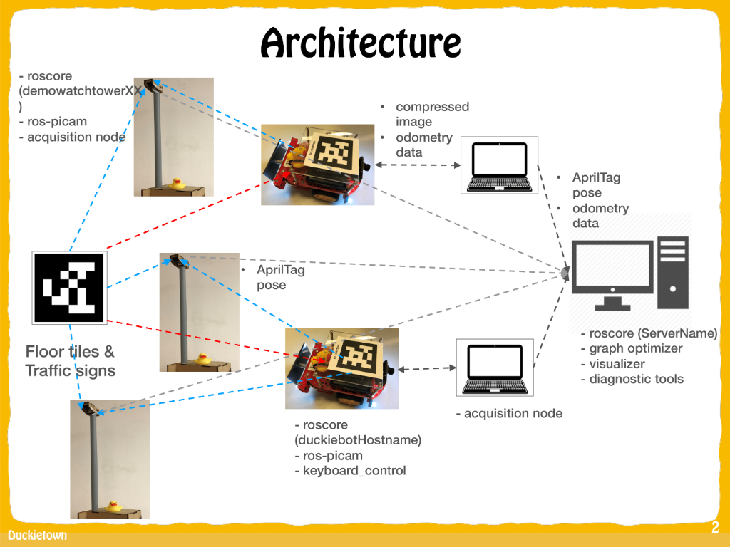
Initially, we used Duckietown to demonstrate autonomous technologies for our corridor project. However, we later secured funding and set up the Autonomous Robotics Innovation Center (ARIC), where we now use Duckietown for a broader robotics program. In ARIC, we teach students ROS, Python, Linux, and the documentation that comes along with Duckietown. Additionally, we plan to integrate railroad intersections with Duckietown, thanks to grant funding from Knorr-Bremse Global Care program in Germany, a train parts manufacturer involved in autonomous train systems.
“We’re seeing that students with very minimal computer science education can jump right into Duckietown and excel”.
Graham Dodge
Yes, we are considering names like Duckierail or Duckietrains. This project aims to develop open-source solutions for Duckiebots to interact with trains and railroad crossings. We are excited to collaborate with the Knorr-Bremse Global Care program, who provided the funding, to showcase rail systems in a smart, connected infrastructure with autonomous vehicles.
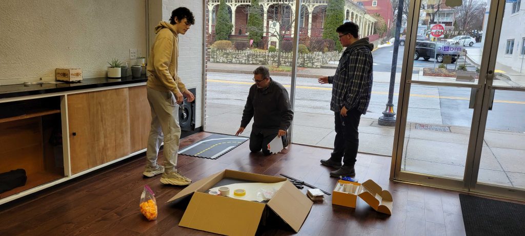
Absolutely! We started with a small MOOC kit, and despite lacking an internal instructor, two student interns managed to get the Duckiebots up and running within three months. The hands-on experience has been rewarding for them, and it’s remarkable how much they’ve learned. We are now expanding the program and have plans to engage with local colleges as well.
Yes, absolutely! Our goal is to set up an apprenticeship program for career pathway development. By providing students with hands-on experience through Duckietown, we aim to make them more attractive to local employers in the robotics industry. The students are already gaining valuable skills that match or even exceed those of some graduate students seeking internships with the same employers.
“We’ve had industry professionals and
local employers look at what we’re teaching and say that what our
high school interns are learning and building with Duckietown is more advanced – and
more industry relevant – than most of the undergraduate students they’ve seen”.Graham Dodge
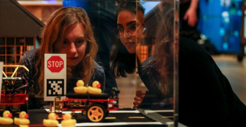
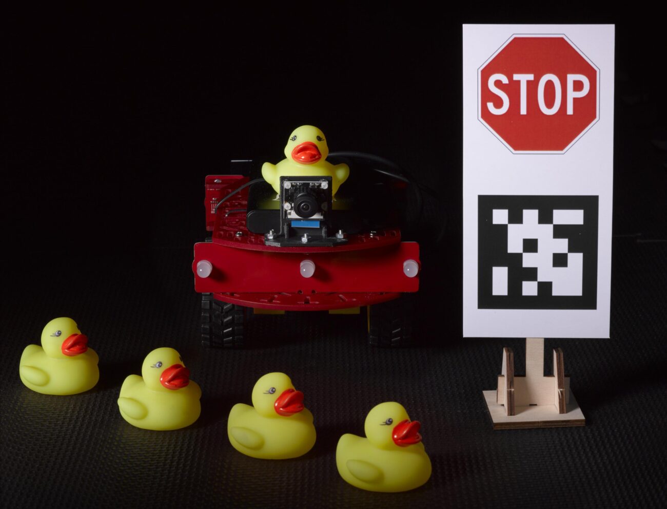
The Duckietown platform enables state-of-the-art robotics and AI learning experiences.
It is designed to help teach, learn, and do research: from exploring the fundamentals of computer science and automation to pushing the boundaries of human knowledge.
Get Started with Duckietown!
Find out more use cases
Are you an instructor, learner, researcher or professional with a Duckietown story to tell? Reach out to us!